

Precoding in 5G

1. Introduction
In 5G NR, precoding is the mathematical operation that converts the spatial layers of PDSCH data into signals for the available transmit antenna ports / RF chains. Beamforming is what those weighted signals ultimately produce in space.
The key relationship is
x=Ws
where:
s∈C^(N_L×1)
is the vector of data symbols on the PDSCH layers,
W∈C^(N_TX×N_L )
is the precoding matrix, and
x∈C^(N_TX×1)
contains the signals transmitted through the antenna ports/RF chains.
TS 38.211 describes this layer-to-antenna-port precoding operation, while TS 38.214 defines how CSI feedback such as RI/PMI/CQI is determined and used for downlink transmission assumptions.
Why do we need precoding?
Suppose the gNB has 32 transmit paths and the UE can support 4 spatial layers.
Without precoding, you could imagine something crude like:
Layer 0 → Antenna 0
Layer 1 → Antenna 1
Layer 2 → Antenna 2
Layer 3 → Antenna 3
and the remaining antennas would contribute nothing useful.
That wastes the antenna array.
Instead, precoding allows every layer to be transmitted through multiple antenna elements with carefully chosen amplitude and phase.
For example:

The weights are selected so that at the UE:
wanted layer energy adds constructively;
different layers remain sufficiently separable;
interference is reduced;
antenna-array gain is obtained.
So precoding simultaneously enables three major benefits:
Beamforming + Spatial Multiplexing + Interference Control
2. Precoding versus beamforming
These terms are closely related but not identical.
Beamforming
Beamforming controls the spatial direction or shape of RF energy.
For one layer: s_0may be transmitted from many antenna elements:
x_m=w_m s_0
with phase progression across antennas.
For example:
TX0: 1∠0°
TX1: 1∠−30°
TX2: 1∠−60°
TX3: 1∠−90°
...
Those phase offsets make the radiated signals combine strongly toward a selected direction.
Precoding
Precoding is the more general operation:
x=Ws
It can simultaneously:
steer Layer 0 toward one effective eigen-direction;
steer Layer 1 through another spatial direction;
preserve orthogonality between layers;
suppress interference;
distribute power across antennas.
Therefore:
Beamforming can be considered one outcome/application of precoding.
For multi-layer MIMO, precoding is more than simply steering one beam.
3. What information does the gNB use to choose a precoder?
This is where RI, PMI, CQI, CRI and sometimes LI enter.
A simplified CSI loop is:

The most important inputs are:
channel estimate;
RI;
PMI;
CQI;
CRI;
LI in certain reporting configurations;
gNB proprietary channel information and scheduler constraints.
Let's look at them individually.
Channel matrix
Fundamentally, precoding depends on the radio channel.
For a MIMO link:
y=Hx+n
where:
H is the MIMO channel matrix.
If the gNB has 32 effective transmit dimensions and the UE has 4 receive antennas:
H∈C^(4×32)
Conceptually it contains the channel coefficient from every TX dimension to every UE receive antenna.
For example:
H=[(h_11&h_12&⋯&h_1,32@h_21&h_22&⋯&h_2,32@h_31&h_32&⋯&h_3,32@h_41&h_42&⋯&h_4,32 )]
The ideal precoder would exploit this channel.
But in FDD-like CSI acquisition, the gNB generally does not obtain the complete instantaneous DL channel directly from reciprocity.
Instead, the UE measures CSI-RS and reports a quantized representation such as PMI and RI.
RI — Rank Indicator
RI tells the gNB how many parallel spatial layers the UE believes the channel can support.
For example:
RI = 1
means:
The channel currently appears suitable for approximately one useful spatial layer.
Whereas:
RI = 4
suggests:
Four layers may be supported with adequate separation.
Mathematically, this relates to the usable rank of:
H or the number of strong spatial eigenmodes.
For an 8-layer capable system:
RI∈{1,2,…,8}
depending on UE capability and CSI configuration.
But RI does not force the gNB to transmit that many layers.
The scheduler may decide:
UE reports RI = 4
gNB schedules only 2 layers
because of:
load;
interference;
implementation policy;
BLER history;
power limitations.
PMI — Precoding Matrix Indicator
PMI is probably the most important parameter when discussing precoding.
The UE evaluates a predefined set of candidate precoding matrices called a codebook.
Conceptually:
W0
W1
W2
W3
...
W127
The UE asks:
Which allowed precoder gives me the best expected performance for the selected rank?
It then reports an index:
PMI = 37
That does not normally mean that the UE sends all complex antenna weights directly.
It means:
· Use the codebook entry identified by this PMI.
TS 38.214 explicitly uses a precoding matrix corresponding to the reported PMI when the CSI report quantity includes PMI, such as cri-RI-PMI-CQI or cri-RI-LI-PMI-CQI.
This is a very important distinction.
CQI — Channel Quality Indicator
CQI answers a different question:
With the assumed rank and precoder, approximately what modulation/coding efficiency could be supported at the target BLER?
So:
· PMI → How should spatial transmission be shaped?
· RI → How many spatial layers?
· CQI → How aggressively can each transmission be coded/modulated?
Example:
· RI = 4
· PMI = 21
· CQI = 13
may lead the scheduler to select something like:
· 4 layers
· selected codebook precoder
· high MCS
But CQI does not itself determine the precoding weights.
CRI — CSI-RS Resource Indicator
CRI tells the gNB which CSI-RS resource the UE selected.
This becomes especially important in beam management.
Suppose the gNB transmits four CSI-RS resources corresponding roughly to four candidate transmission beams:
CSI-RS Resource 0 → Beam A
CSI-RS Resource 1 → Beam B
CSI-RS Resource 2 → Beam C
CSI-RS Resource 3 → Beam D
UE measurements might be:
Beam A = −86 dBm
Beam B = −78 dBm
Beam C = −91 dBm
Beam D = −83 dBm
The UE may report:
CRI = 1
meaning CSI-RS resource 1 is preferred.
Then PMI further refines the spatial precoding inside the selected CSI hypothesis.
You can think approximately:
· CRI → coarse beam/resource selection
· PMI → finer MIMO precoding structure
although practical implementations can be more sophisticated.
What is LI?
LI = Layer Indicator.
It is easy to confuse LI with RI.
They are not the same.
RI says:
How many layers can be supported?
LI is associated with reporting assumptions for a particular strongest/preferred layer in certain CSI reporting modes.
For example, TS 38.214 supports report quantities including:
cri-RI-LI-PMI-CQI
alongside:
cri-RI-PMI-CQI
LI can help identify layer-related quality information used in CQI calculation/reporting.
For normal engineering discussions of downlink precoding, the most central parameters remain: (CRI, RI, PMI, CQI)
LI is more specialized.
4. Does the gNB use only UE PMI?
No.
A commercial 5G gNB normally combines several inputs:

Especially in TDD massive MIMO, the gNB can exploit uplink SRS and channel reciprocity.
Therefore the final physical antenna weights may be more sophisticated than simply copying a 3GPP PMI codebook matrix.
The standardized CSI provides an interoperable reference/interface.
The internal beamformer can still be vendor proprietary.
How PMI becomes a precoding matrix
Consider a simpler example first.
Assume:
4 antenna ports
2 PDSCH layers
The layer vector is:

Suppose the selected PMI corresponds conceptually to:

Then:
x=Ws
so:
x_0=1/2(s_0+s_1 )
x_1=1/2(s_0-s_1 )
x_2=1/2(s_0+js_1 )
x_3=1/2(s_0-js_1 )
Notice something important:
Each antenna port contains a combination of both layers.

The UE sees an effective channel:
H_eff=HW
and tries to separate the two layers.
The most useful equation
For understanding the complete downlink MIMO system, use:
y=HWs+n
where:
s="PDSCH layer symbols"
W="precoder"
H="radio channel"
y="received UE signal"
The purpose of precoding is to choose such that: HW
looks as favorable as possible.
Ideally:
Layer 0 → strong path
Layer 1 → strong independent path
Layer 2 → strong independent path
...
while minimizing cross-layer interference.
Now take your 32TR example
Assume a 32TR massive-MIMO radio.
A common conceptual antenna arrangement might be:
32 RF TX/RX paths
feeding 32 dual-polarized/effective antenna branches, depending on the radio architecture.
Now assume:
UE supports 8 layers
RI = 8
gNB decides to schedule 8-layer PDSCH
The PDSCH layer vector is:

The full physical precoding matrix could conceptually have dimensions:
W32×8
Then:
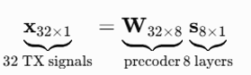
This is the central idea.
5. What does a precoder mean?
It contains: 32×8=256 complex weighting coefficients.
Conceptually:

Each coefficient has: Amplitude + Phase
For example:

So TX branch 17 could transmit:

All eight layers may therefore contribute to one physical transmit chain.
Does PMI directly contain 256 weights?
Usually no.
This distinction is extremely important in massive MIMO.
The UE does not normally send:
w00 = ...
w01 = ...
...
w31,7 = ...
That would create enormous feedback overhead.
Instead, the UE reports a compact set of indices.
For CSI codebooks, the available CSI-RS port counts can extend to values such as:
P∈{1,2,4,8,12,16,24,32}
and the standardized PMI represents an entry or combination of entries from the configured codebook structure.
The gNB reconstructs the appropriate standardized precoding hypothesis from those indices.
6. A more realistic 32TR architecture
In a practical massive-MIMO radio, it is useful to distinguish:

So the processing may resemble:

This distinction matters because a 32TR radio is not simply:
32 independent PDSCH antenna ports.
The relationship between standardized antenna ports and physical elements is implementation specific.
Example: UE measures CSI-RS
Suppose the gNB transmits a 32-port CSI-RS.
The UE estimates: HCSIand discovers eight reasonably strong spatial modes.
Assume it reports:
· CRI = 2
· RI = 8
· PMI = codebook entry X
· CQI = 12
The report roughly means:
CRI = 2
CSI-RS resource 2 gave the preferred channel hypothesis.
RI = 8
I believe eight spatial layers are usable.
PMI = X
For rank 8, this codebook precoder provides favorable expected performance.
CQI = 12
With this CSI assumption, approximately this spectral efficiency appears supportable.
7. gNB scheduler decision
The scheduler may decide:
· RI reported = 8
· Requested traffic = very high
· SINR = strong
· BLER history = low
· Cell load = moderate
Therefore:
Schedule:
· 8 layers
· MCS 20
· 100 PRBs
· PMI-based precoder
But if BLER recently increased:
· RI report = 8
does not necessarily mean: Use 8 layers.
The scheduler could choose:
· 4 layers
· MCS 18
for robustness.
Layer mapping before precoding
Suppose a transport block becomes modulation symbols:
d0 d1 d2 d3 d4 d5 ...
For eight layers, layer mapping distributes them approximately as:
Layer 0: d0 d8 d16 ...
Layer 1: d1 d9 d17 ...
Layer 2: d2 d10 d18 ...
...
Layer 7: d7 d15 d23 ...
Now every OFDM resource position has a layer vector:

Precoding then produces 32 weighted outputs:
x=Ws
8. How does the UE separate eight layers?
The DMRS is critical here.
If eight PDSCH layers are transmitted, the corresponding PDSCH antenna ports have orthogonal/separable DMRS structures.
The UE estimates the effective precoded channel.
It does not necessarily need to know every internal 32-element physical array coefficient.
What matters to the UE is approximately:
H_eff=HW

This is a major concept:
The UE normally decodes the effective channel created by the gNB precoder, rather than reconstructing the gNB's physical 32-element beamforming implementation.
How PMI relates to DMRS
· PMI helps the gNB choose the spatial transformation.
· DMRS helps the UE estimate the effective result of that transformation.
Thus:

This is why PMI does not have to be explicitly known at the UE again during PDSCH decoding in the same way you might initially expect.
The DMRS embodies the effective PDSCH spatial channel.
9. Codebook-based precoding
In codebook-based operation, belongs to a predefined collection.
Suppose the available choices were conceptually:
W0,W1,W2,…,WN
The UE evaluates:
SINR(Wi )
or an equivalent predicted throughput metric.
Suppose:
W_17
performs best.
UE reports:
PMI = 17
Then the gNB knows:
W=W17subject to the configured codebook interpretation.
This dramatically reduces feedback compared with sending every complex matrix coefficient.
Type-I and Type-II CSI codebooks
For massive MIMO, codebooks become more sophisticated.
A high-level way of understanding them is:
Type-I codebook
Provides relatively compact beam/direction-oriented CSI.
Useful when feedback overhead must be limited.
Conceptually:
Select beam basis + select phase/co-phasing + select rank
Type-II codebook
Provides higher-resolution channel information by allowing combinations of multiple spatial beams/components.
It can better approximate the UE's actual channel but requires more feedback.
Conceptually:

where Vb are spatial basis beams and Cb,l are weighting coefficients.
That is much closer to detailed channel reconstruction.
10. 32TR beamforming example
Let's simplify the 32TR array to one layer first.
Suppose Layer 0 should be steered toward the UE.
The precoding vector could conceptually look like:

Then:
x=w0 * s0
The phase progression makes the radiated waves align toward the desired angle.
That is classical beam steering.
Now extend it to eight layers
For eight layers:

Each column represents the spatial weights for one layer:
Column 0 → Layer 0 spatial precoder
Column 1 → Layer 1 spatial precoder
...
Column 7 → Layer 7 spatial precoder
So:
W32×8=[w0 w1 … w7]
Each wl is a 32-element vector.
The scheduler/beamformer attempts to choose these vectors so that:
Hw_0, Hw_1,…,Hw_7
remain strong and sufficiently independent.
Why can't we simply use eight different beams?
Because eight spatial layers do not necessarily mean eight geographically separate narrow beams.
That is another common misconception.
For a single UE, spatial multiplexing exploits different propagation modes.
Those may arise from:
angular separation;
multipath reflections;
polarization;
antenna geometry;
scattering.
For example:
Layer 0 → dominant LOS/eigenmode
Layer 1 → reflected spatial mode
Layer 2 → cross-polarized mode
Layer 3 → another independent multipath mode
...
The beams can overlap physically.
The important condition is that the resulting effective channel matrix has enough rank.
SVD gives the intuitive ideal case
Suppose:
H=UΣV^H
from singular-value decomposition.
Then the theoretically attractive precoder is related to:
W = V
or the first right-singular vectors.
For rank 8:
W=[v_1 v_2 … v_8 ]
The effective channel becomes:
HW=UΣ
which approximately creates independent parallel channels.
This is conceptually what good MIMO precoding tries to achieve.
But standardized codebook feedback gives a quantized approximation rather than letting the UE send arbitrary V .
11. Codebook versus non-codebook / proprietary beamforming
For actual commercial massive MIMO:
3GPP codebook + UE CSI + vendor algorithms
often coexist.
The gNB might use:
CSI-RS PMI;
UL SRS reciprocity;
long-term covariance;
beam history;
interference covariance;
Zero Forcing;
MMSE;
regularized ZF.
For example, a simple ZF precoder concept is:

The idea is:

which reduces cross-layer/user interference.
A regularized/MMSE-like precoder may instead use:

giving a better noise/interference trade-off.
These internal algorithms are typically vendor specific; standardized PMI can act as one CSI input rather than exposing the complete implementation.
12. SU-MIMO 32TR × 8-layer example
Assume one UE:
gNB = 32TR
UE RX antennas = 8
UE capability = 8 layers
The physical channel is:
H_(8×32)
UE reports:
RI = 8
PMI = P
CQI = 13
gNB constructs:
W(32×8)
and transmits:
x(32×1) =W(32×8) s(8×1)
UE receives:
y(8×1)=H(8×32) W(32×8) s(8×1)+n
If the precoder is good:
HW
might approximately resemble:

Then eight layers can be recovered with relatively low mutual interference.
MU-MIMO makes precoding even more important
Suppose instead:
UE1 = 4 layers
UE2 = 2 layers
UE3 = 2 layers
Total: 4+2+2= 8
layers.
Now the 32TR array sends all three UEs on overlapping time/frequency resources.
The precoder must not only beamform toward each UE but suppress interference between them.
Conceptually:
W=[W_UE1 W_UE2 W_UE3 ]
Desired outcome:
· UE1 sees strong UE1 layers
and weak UE2/UE3 leakage
· UE2 sees strong UE2 layers
and weak UE1/UE3 leakage
· UE3 sees strong UE3 layers
and weak UE1/UE2 leakage
This is where ZF/MMSE-style massive-MIMO precoding becomes extremely valuable.
13. What are the outputs of precoding?
The direct output is a set of weighted complex symbols:
x_0,x_1,…,x_(N_TX-1)
for the transmit dimensions.
But operationally, the outcomes are more useful to think about as:
spatially directed energy;
selected number of PDSCH layers;
effective beam shape;
improved received SINR;
layer separation;
reduced inter-user interference;
antenna-array gain;
improved throughput.
You could summarize it as:

An important correction regarding CQI
CQI is not normally fed mathematically into W in the same direct sense as PMI/channel information.
A better understanding is:

But the scheduler jointly optimizes them.
For example:
PMI A + Rank 8 → SINR per layer too low
could result in:
Rank 4 + different PMI
and a higher CQI/MCS per layer yielding more total throughput.
Thus RI, PMI and CQI are coupled during optimization even though they represent different quantities.
14. Practical protocol-test example
Suppose your UE log shows:
CSI report
----------
CRI = 3
RI = 4
PMI = 52
CQI = 14
The next PDSCH shows:
Layers = 4
MCS = 25
PRBs = 250
DMRS ports = 1000–1003
HARQ PID = 7
RV = 0
As a test engineer, check:
1. CSI consistency
Was CSI-RS Resource 3 actually configured?
2. Rank consistency
UE reported:
RI = 4
and gNB scheduled:
4 layers
Reasonable.
3. PMI evolution
Did PMI change rapidly?
Example:
52 → 18 → 61 → 4 → 57
with a stationary UE.
That can indicate unstable CSI estimation or interference.
4. CQI versus MCS
CQI = 14
MCS = aggressive
may be reasonable.
But if:
CQI suddenly drops to 7
gNB keeps MCS 27
you may see BLER rise.
5. DMRS ports
Four layers require corresponding effective DMRS-port support.
6. PDSCH BLER
If BLER is high despite:
SINR = 30 dB
CQI = 15
investigate:
precoding mismatch;
CSI aging;
bad beam selection;
PMI mismatch;
DMRS quality;
PA compression;
calibration;
reciprocity errors.
Massive MIMO calibration becomes critical
For your 32TR example, imagine the intended weight on two branches is:
w_0=1∠0^∘
w_1=1∠-30^∘
but due to RF-chain calibration error the actual second branch becomes:
w_1^'=0.8∠-5^∘
The intended beam no longer forms correctly.
Across 32 paths, small amplitude/phase errors can significantly degrade:
beamforming gain;
null depth;
MU-MIMO interference suppression;
EVM;
layer SINR.
That is why massive-MIMO systems require accurate TX/RX array calibration.
A system can have:
· Good conducted power
· Good average RSRP
yet poor PDSCH performance because the spatial precoder is wrong.
15. PMI aging is another practical issue
Suppose:
· t = 0 ms:
UE measures CSI-RS reports PMI = 42
· t = 4 ms:
UE reports PMI 42
· t = 8 ms:
gNB schedules PDSCH using that CSI
If the UE is moving rapidly, the actual channel may already have changed:
H(t=8)≠H(t=0)
Then:
W_PMI42
may no longer be optimal.
Consequences:

This is called CSI aging.
It becomes particularly important with:
high mobility;
high carrier frequency;
high rank;
narrow beams.
16. Precoding and beamforming in hybrid architectures
A 32TR radio may also employ multiple stages of weighting.
Conceptually:
W_total=W_RF W_BB
where:
W_BB
is digital baseband precoding and
W_RF
represents RF/analog beamforming.
Then:
x = W_BB W_RF s
In a fully digital 32TR massive-MIMO radio, there may effectively be one controllable digital path per TRX.
In hybrid architectures, the number of independent digital streams can be smaller than the number of antenna elements.
This is why the statement:
“32 antennas require 32 digital layers” is incorrect.
You could have:
· 32 antenna/TRX branches
· 8 digital PDSCH layers
quite naturally.
A useful analogy model
Think of an orchestra.
Layers
Eight different songs/data streams:
L0 L1 L2 L3 L4 L5 L6 L7
Precoder
The conductor decides how strongly each of the 32 loudspeakers should play each song and with what phase.
32TR array
32 loudspeakers.
Channel
The room acoustics.
UE
Eight microphones trying to recover the eight songs.
A good precoder causes:
Microphone/eigenmode 1 → mostly Layer 0
Microphone/eigenmode 2 → mostly Layer 1
...
A poor precoder causes all songs to overlap heavily.
That is the essence of MIMO precoding.
17. Summary
The full 32TR / 8-layer chain can be viewed as:

The four CSI terms can be remembered very simply:
· RI="How many layers?"
· PMI="Which spatial precoder?"
· CQI="How aggressive can MCS be?"
· CRI="Which CSI-RS/beam hypothesis?"
And the essential massive-MIMO equation is:
y=HWs+n
For a 32TR, 8-layer example:

is the most useful mathematical picture to keep in mind.
One subtle but critical point for field debugging is that PMI is a UE recommendation describing a standardized precoding hypothesis; it should not be interpreted as the exact 32 physical antenna weights inside the radio. Commercial massive-MIMO gNBs can combine CSI feedback with SRS, reciprocity, calibration and proprietary ZF/MMSE/beamforming algorithms before generating the actual RF weights.
18. References
1. 3GPP TS 38.211 — NR; Physical Channels and Modulation.
2. 3GPP TS 38.212 — NR; Multiplexing and Channel Coding.
3. 3GPP TS 38.214 — NR; Physical Layer Procedures for Data.
4. 3GPP TS 38.215 — NR; Physical Layer Measurements.
5. 3GPP TS 38.213 — NR; Physical Layer Procedures for Control.
6. 3GPP TS 38.331 — NR; Radio Resource Control (RRC) Protocol Specification.
7. Erik Dahlman, Stefan Parkvall, Johan Sköld — 5G NR: The Next Generation Wireless Access Technology, Academic Press/Elsevier.
8. Sassan Ahmadi — 5G NR: Architecture, Technology, Implementation, and Operation of 3GPP New Radio Standards, Academic Press.
9. Emil Björnson, Jakob Hoydis, Luca Sanguinetti — Massive MIMO Networks: Spectral, Energy, and Hardware Efficiency, Foundations and Trends in Signal Processing.
AI Disclosure: AI-assisted tools were used where appropriate for content organization, language refinement, and explanatory support.


Comments